Jet Blast Turbine Engine Cleaning Media
Jet Blast is a combustible media made from nut shells. Perfect as to
abrasiveness. Spent catalyst is too abrasive and rice not abrasive enough for as
good cleaning job.
Laboratory experiments have indicated that all media compounds may be somewhat
corrosive and leave an adherent scale if they are deposited on hot metal surfaces (i.e. at
1500°F). Field experience, however, has indicated that the chance of such media
actually depositing on hot components is fortunately very remote.
Dirt, oil, mist, salt and other foreign substances contained in the air atmosphere may
deposit upon compressor blading during operation of the Gas Turbine. The thermal
efficiency and output of the unit is gradually lowered as the amount of this fouling
increases. These deposits can be removed and output and efficiency restored by the
intermittent use of equipment and cleaning procedures.
Inject Jet Blast into the compressor inlet downstream of any filter washer or silencing
arrangement and into an area where the velocity is sufficiently high to carry the media
into the compressor inlet. Ahead of the inlet flange has generally been found
acceptable. Method of injection will vary with machine and with some units may only
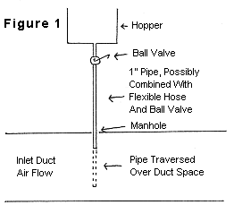
involve throwing the Jet Blast discreetly into the inlet. Another simple way is to
feed Jet Blast through a pipe inserted into the inlet duct feeding from a small hopper
with rate of flow controlled by a ball valve. Jet Blast should be injected until
there is no more improvement in output and exhaust temperature. The amount of
cleaning will vary with machine experience. Feeding rate is generally extended over
a period of fifteen to twenty minutes. Generally, a minimum of two hundred pounds
per machine per month for Turbines in the 3000 H.F. range. The intervals between
cleaning will depend upon the atmosphere to which the Gas Turbine is installed and the
proximity of such contaminant sources as oil-vent lines. Often it is best to clean
weekly, however, two week periods under some conditions have proved satisfactory.
Care should be taken to protect any critical areas peculiar to the particular
installation such as bearings, controls, sealing air, etc. When cleaning Gas Turbine
units which are equipped with separators in the atomizing air or bearing sealing air
circuits, open the blow-down valves (this will provide approximately 10 percent flow).
Some Gas Turbines do not have bearing sealing air circuits and bearings are sealed
by air drawn through the bearing seals by a vapor extraction system. On such units,
special arrangement for bearing protection is not necessary, except to reduce vapor
extractor oil tank pressure to one-half inch of water vacuum (negative pressure).
When cleaning Gas Turbines which have pneumatic control systems, the control air should
be supplied from a source other than the axial flow compressor of the Turbine being
cleaned.
When cleaning Turbines which have inlet air washers, the washers should be shutdown at
least one-half hour prior to cleaning to assure that the surfaces of the air path through
the compressor and ducting will be dry. This will prevent the cleaning compound from
adhering to these surfaces.
Care should be taken to assure that compressor deposits which might be corrosive at
elevated temperatures are not cleaned from the compressor onto the Turbine buckets and
nozzle partitions. This is a concern particularly with slat (NaCl) accumulations on
units located in marine atmospheres. In such instances cleaning should be done with
engine idle or greatly reduced load (i.e. at lower temperatures in the Turbine section).
Cleaning Procedures
A procedure equivalent to the outlined below has been found satisfactory.
Equivalent methods may be used, however, depending upon the unit design.
- Remove the injection nozzle hole cover from the inlet air duct and install the injection
nozzle pipe as shown in Figure 1. The nozzle should
preferentially be capable of insertion to different depths across the duct to get more
even distribution of the compounds into the compressor.

- Operate any valving or equipment on the Gas Turbine unit in accordance with Paragraph
Six.
- Fill and/or replenish the injection nozzle hopper with Jet Blast compounds.
- Run the Gas Turbine unit as idle speed (or the lowest practical speed for most effective
cleaning as determined by actual operating experience) as it has been observed that
cleaning is often better at the lower compressor speeds. This may be because of a
reduced tendency for the Jet Blast to be disintegrated or thrown to the rotor blade types.
- Control the injection rate evenly over the cleaning time span, such as by adjusting the
ball valve shown in Figure 1.
- Run the Turbine an additional 5 minutes to assure that all the Jet Blast has been purged
from the unit, running at full load.
- Restore the valving and equipment.
| Chemical Composition % (Based
on Original Sample) |
Exposure Test with AISI 310 S.S. |
| 940°F-8 hrs |
1500°F-8 hrs |
| Adherent |
Adherent |
| Product |
Ash |
S |
Na |
Cl |
K |
P |
Ca |
Mg |
Si |
Al |
Corr. |
Ash |
Corr. |
Ash |
| Jet Blast |
2.2 |
.03 |
.01 |
.02 |
|
|
.2 |
.02 |
.002 |
.002 |
None |
None |
Some |
Some |
|
|